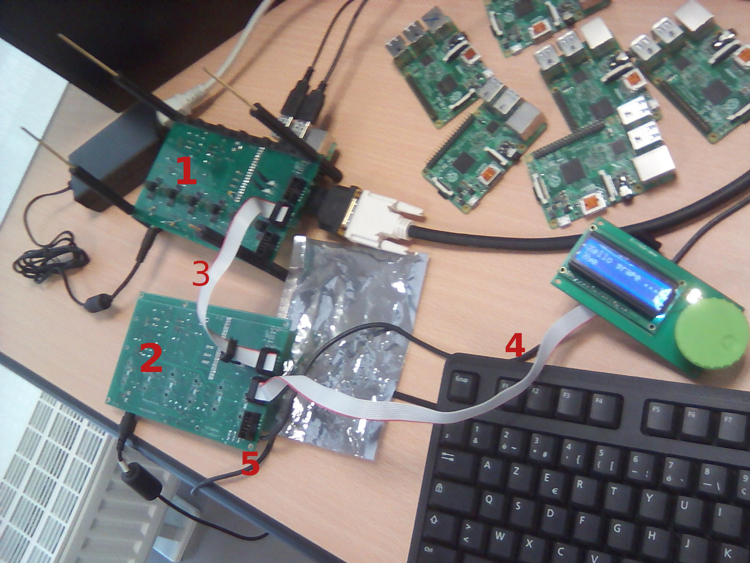
A connection using the I2C bus looks like the picture below:

A few things to note (the enumeration number is presented in the image):
- Only one PCB has a master PI. You can see how two USB ports of this PI are used for the mouse and keyboard. You can also see it connected to a screen.
- The second PCB has its own power supply. Remember, each stack is independently powered.
- PCB 2 can be accessed from PCB 1 using the I2C bus (white ribbon cable).
- The screen is connected to PCB 2 but it is controlled from the master in PCB 1 (again white ribbon cable).
- The empty slot in PCB 2 is special (is the same for every stack). The slot is used to bridge the workers to the master. As a result, you cannot use it to chain many stack. For that, only the slots 1 and 2 are available.
Finally, you can also notice that there are no workers connected – this is a good way of testing the PCB without the risk of burning a worker PI.
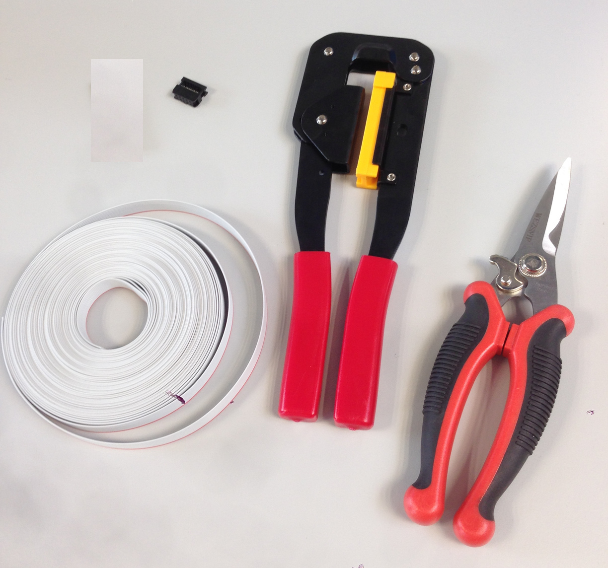
Making cables to bridge the stacks
There is nothing special about this, it is just boring and error-prone. We advise to connect the red marker in the cable to the marker in the connector. You need the following materials and tools:

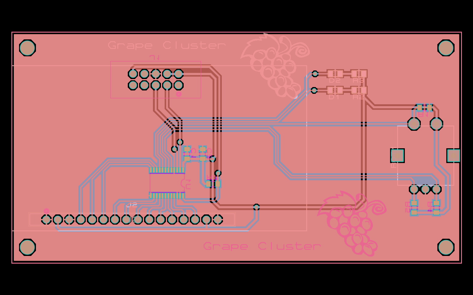
The screen.
An optional component you can connect to the cluster is the screen. To build it, you must print the following PCB (Gerber File):

Afterwards you can solder the list of components.
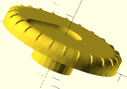
Finally, use a 3D printer to make this fancy button (Model). 
Configuring the jumpers
Testing
For testing, refer to section Master’s configuration