Goal
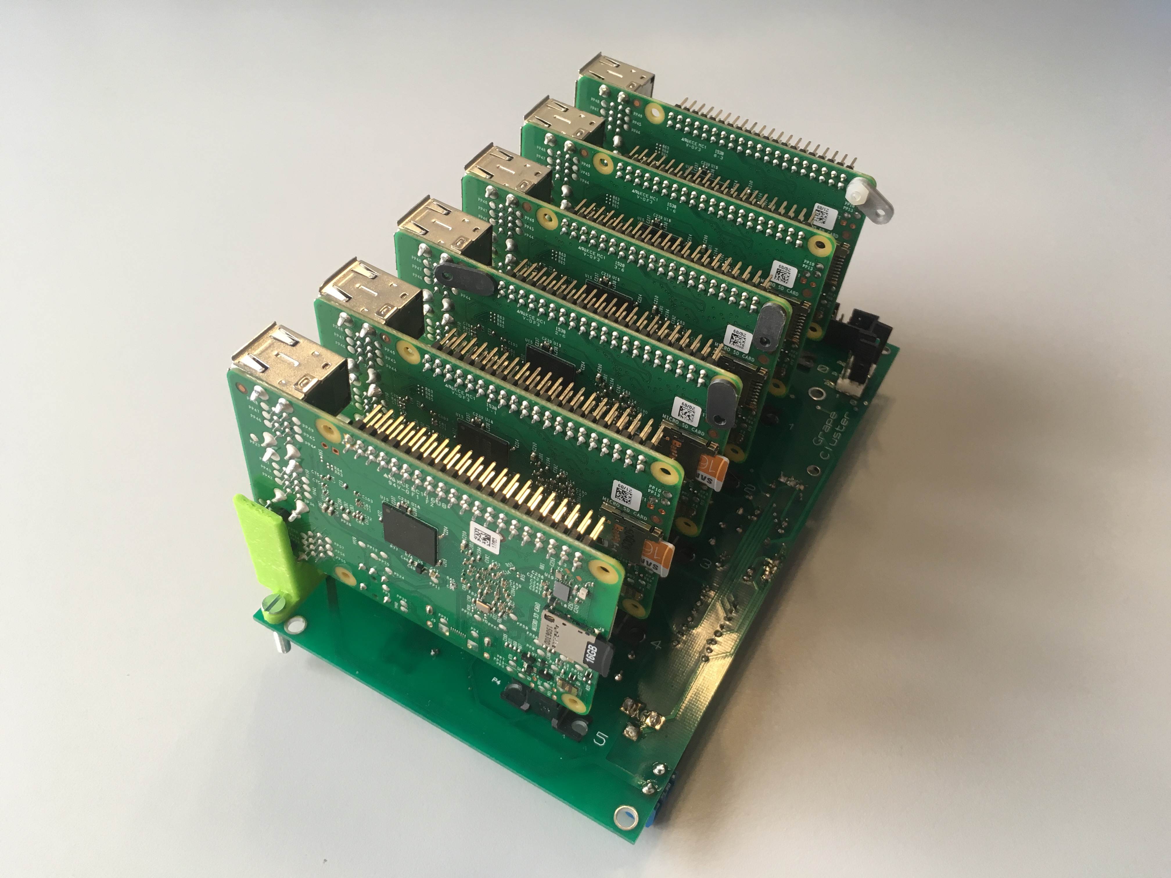
As we mentioned in the overview, it is important to reduce the number of cables needed. For this reason, we designed a custom board that powers a group of PIs – a.k.a stack.
The main function of this custom board it to distribute the power among all the PIs in the stack. In addition, a temperature sensor, a power monitor and a power controller are attached to the board. The temperature sensor and the power monitor are used to collect the local temperature of the stack. Meanwhile, the power controller is used to turn on/off the Raspberry PIs in the stack. Notice that these extra-devices cannot be accessed from any PI in the stack (a.k.a Slaves). Instead, it is accessed by the master using a I2C interface.
Finally, be aware that all stacks are sharing the same I2C interface. They appear in the bus as different devices.
Building the stack
Printing 3D Pieces
- Print three pieces two support and hold the Rasps (Model).For this, you will need a 3D printer at least as large as the Ultimaker 2.

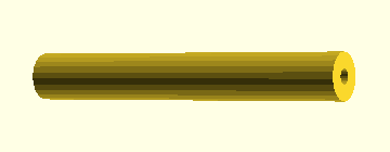
- Print short spacer to support the PCB (Model).
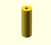
- Print long spacer to support the network switch (Model). For this, you will need a 3D printer at least as large as the Ultimaker 2.
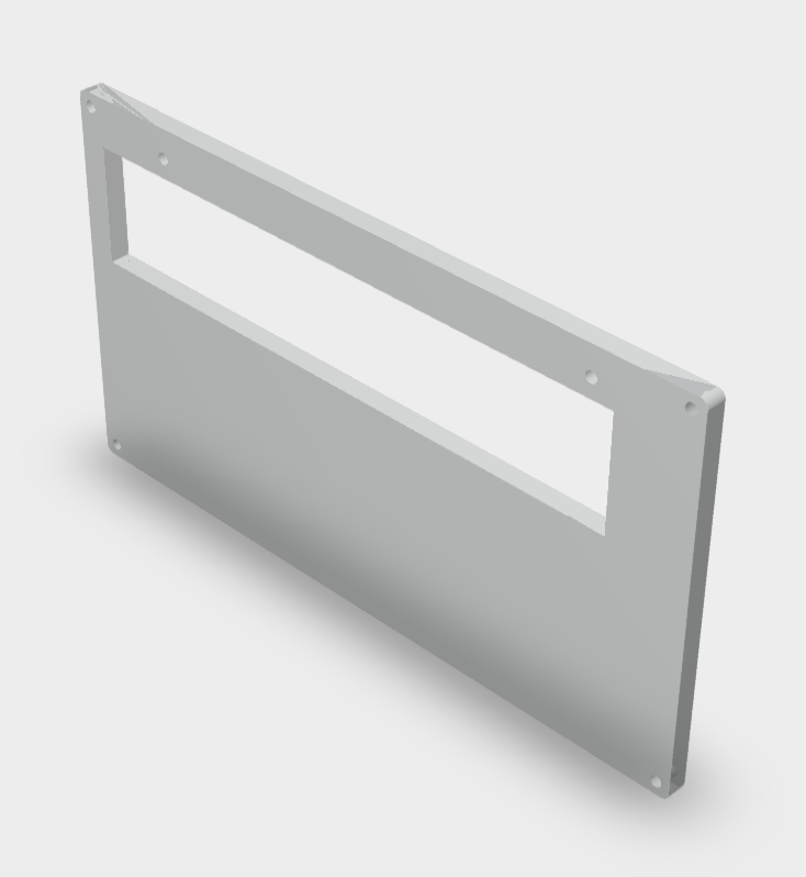
- Cut a pexiglass piece to separate the Rasps and the switch (Model). To use this model you will need a laser cutter.
Making the PCB
The Gerber model of this schematic can be used to print it either yourself or sending it to an online service such as PCBWay.
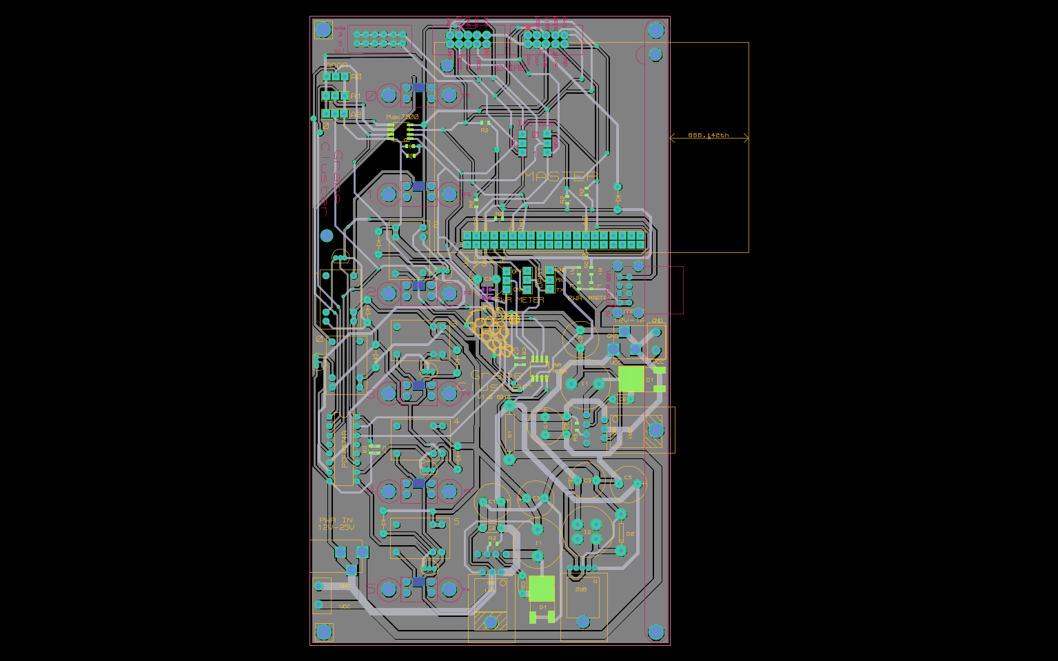
The result of printed this schematic is a PCB as the one shown in the picture below. Observe that there are no components installed. It is possible to order a PCB with the components already included but it is more expensive. Finally, The picture belows shows one side of the PCB, but in practice we must weld components on both sides.
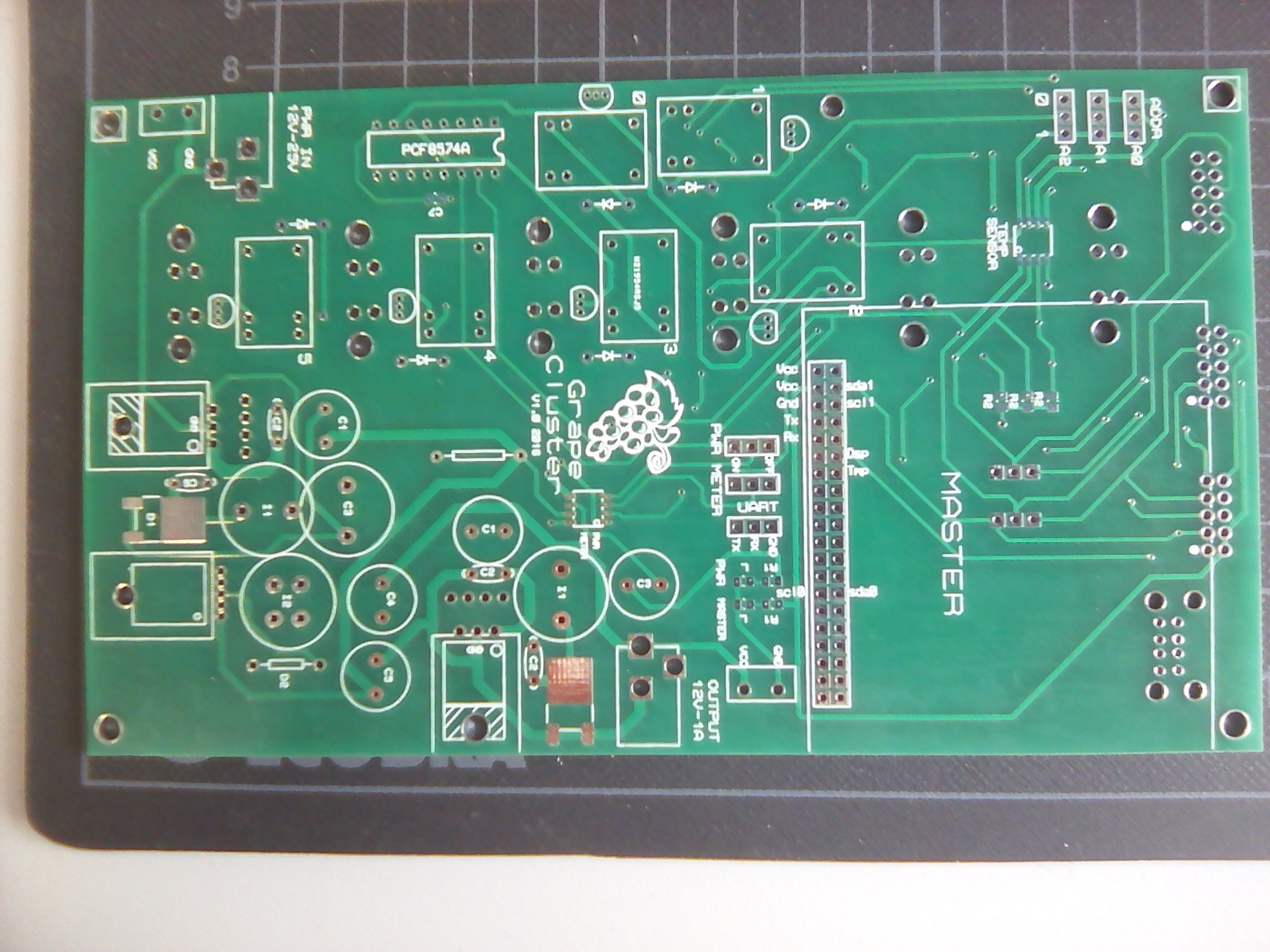
Tips for welding: When welding the micro-usb, only weld the first and last pin. Since the other are really hard to do, it should avoid lot of trouble (short-circuits and related problems)
Assembling
Now it is time to mount the stack; this is a time consuming task. Simply go to a place with space, mount each stack and test it until you get the desired result.
The first step is soldering the electrical components to the PCB. For doing that, we can use the following diagram.
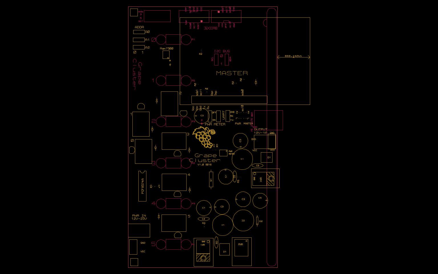
Notice how each component has a label. Using that label you can find the right component to attach using the following table.
| Name | Label in PCB | Quantity | Farnell Ref | Alternative |
|---|---|---|---|---|
| Capa 47uF/50V | C1 | 2 | 1902931 | |
| Capa 100uF/50V | C5 | 1 | 1902932 | |
| Schottky Rectifier (5V) | D1 | 2 | 1697512 | |
| Schottky Rectifier (12V) | D2 | 1 | 2341584 | |
| Capa 330uF/16V | C3 | 4 | 9451102 | |
| Capa 1uF | C7 | 4 | 1759432 | |
| Capa 100nF | C8 | 4 | 1759143 | |
| Relay | Re | 6 | 1094008 | |
| Diode | Standard diode symbol | 7 | 1700871 | |
| Transistors | Beside each Re | 6 | 2283624 | |
| Micro USB | P1-P6. Other side of the board | 6 | 2554967 | |
| Capa 0.01uF | C6 | 2 | 1216435 | |
| Capa 470pF | C2 | 2 | 1100510 | |
| Shunt Jumper | on top of on/off/a{012}/sda/scl | 6 | 2396301 | |
| I/O expander 8bits | PCF8574AN | 1 | 1703443 | |
| Board-To-Board Connector | on/off/gnd/rx/tx/a{012}/sda/scl | 8 | 9731083 | |
| Power Connector | PWR IN/OUTPUT | 2 | 224959 | * |
| Screw terminal | PWR IN/OUTPUT | 2 | ? | * |
| Wire to Board Connector | 2 | 2215304 | ||
| Inductor 330uH | I2 | 1 | 2493162 | |
| Inductor 22uH | I1 | 1 | 2526937 | |
| Heat Sink * | Attached to each SR | 3 | 1703172 | |
| Switching Regulator (12V/1A) | SR1 | 1 | 9488073 | |
| Switching Regulator (5V/5A) | SR2 | 2 | 2492170 | (1) |
| Resistor 5.6k | R3 | 2 | 1100319 | (1) |
| Switching Regulator (5V/5A) | SR2 | 2 | 2492170 | (2) |
| Temperature Sensor * | Max7500 | 1 | 2515642 | |
| Resistor 5.6k | R2 | 5 | 1100319 | |
| Power Monitor * | PWR Monitor | 1 | 2496402 | |
| Shunt resistor * | SR3 | 1 | 1108073 | |
| Board-To-Board Connector (GPIO) | GPIO Master | 1 | 1569232 | |
| Switching Regulator (5V/5A) | SR2 | 1 | 2492170 | |
| Micro USB | P1-P6. Other side of the board | 6 | 2554967 | |
| Relay | Re | 6 | 1094008 | |
| LED | L | 2 | 2497355 | |
| Resistor 2k | R1 | 2 | 2447622 | |
| USB Connector | 1 | 2442536 | ||
| Pin Header | 1 | 1022237 | ||
| Jump-Wires | To connect each Pi | 6 | 563-BC-32673 | Mouser |
| Network Switch | 1 | 2908341 GS608-400PES | Misco |
The Alternative column allows you to choose between two components ; the PCB is compatible with both prints. You have to choose between alternative (1) which is generally cheaper or alternative (2) which has less components (thus the print of R3 should be left empty).
Power connector and screw terminal should not be pluged at the same time. Moreover in the last layout, both 12V output connector share the same print, you will have to choose before soldering.
PCB with components already attached
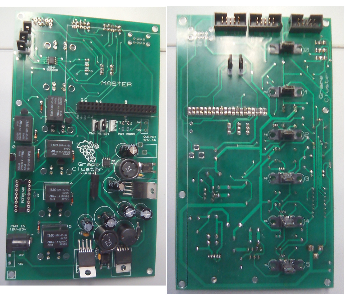
Final assembling
To connect all the elements of the stack follow the following steps:
Step 1: Plug the master if the stack is acting as master.
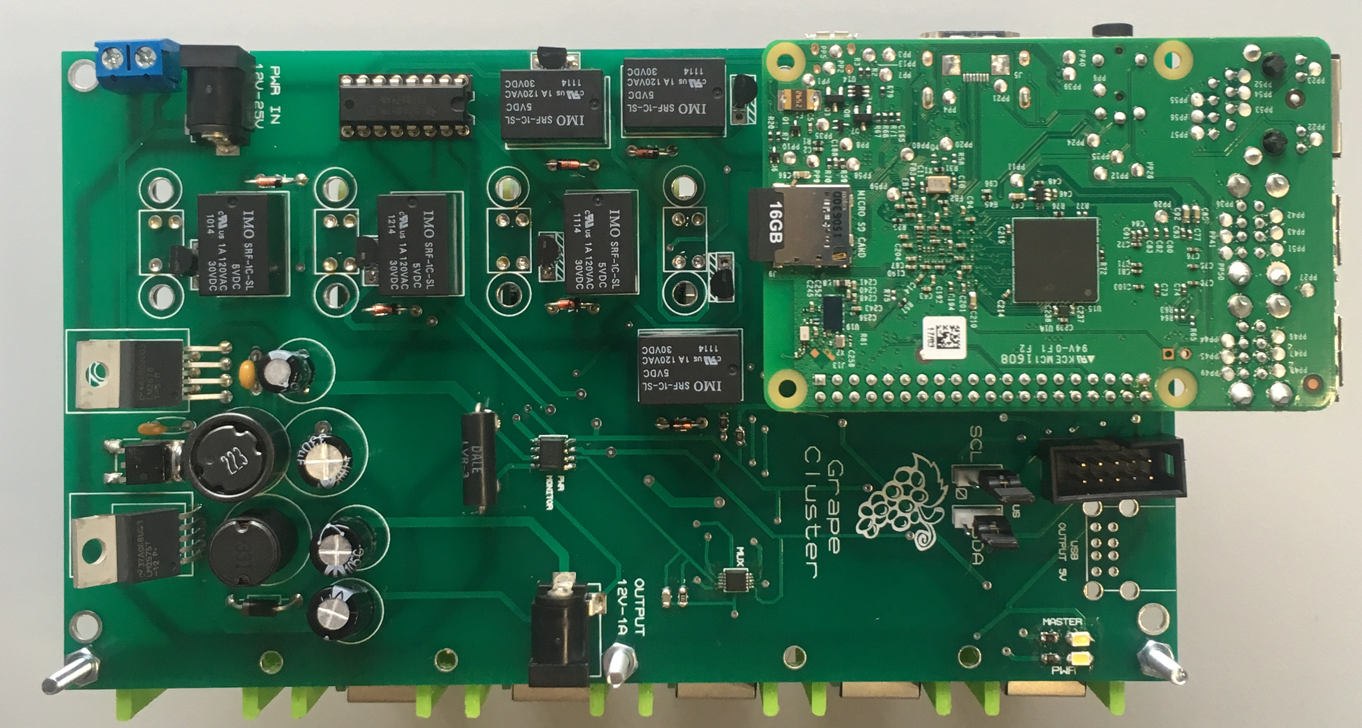
-
Attach the support to the PCB
-
Plug the slaves (Raspbs)
-
Attach the short spacers to the PCB
-
Attach the long spacers to the PCB
-
Put the two remaining supports on top of the Rasps
-
Attach the pexiglass separator to the supports on top of the Rasps
-
Attach
-
Attach the support to the PCB
Testing
It is, of course, a good idea to test every stack before connecting them all together. The easiest way is using the power supply; if everything goes well you shall see four red leds turning on. That should be enough. Nevertheless, you can also check if each Raspberry Pi is really able to boot. This is a good idea because while booting they consume more energy. Hence, prepare four Sd Cards and power on the stack with the SD Cards inserted.
Should you detect a problem, it can be:
- A failure in a cable
- A problem with the custom board
- A problem with the SD Cards
- A problem with the Raspberry Pi
- Ground and Plus inverted (you will see the smoke)